
Spillover Spa Hydraulic Loop: Valve Changeover, Anti-Siphon Check Valve and Weir-Scale Control
A spillover spa can drain toward the pool or lose useful heat when the operating paths are wrong. Review its hydraulic loop as valve changeover, anti-siphon check-valve function and weir-scale control, with separate checks for running and pump-off conditions.
A spillover spa needs an operating-mode schedule before actuator endpoints or check-valve locations are accepted. Trace the suction source, return destination and permitted heating state in pool, spillover, spa and pump-off modes. Then verify the actual changeover and level behavior against that schedule. “Anti-siphon check valve” here means a return-line nonreturn valve intended to resist reverse water transfer; it is not a vacuum breaker, a potable-water backflow assembly or suction-entrapment protection.
Use the pool and spa layout brief to identify shared or separate equipment. The example below is a shared-filtration system with an elevated spa; a dual-equipment installation needs its own hydraulic and controls schedule.
Swipe table horizontally to read all columns.
Scroll horizontally to see all columns →
| Input or item | Value or source | Why it matters |
|---|---|---|
| Water-level difference | Measure both settled levels from one survey datum | Identifies the gravity-driven transfer potential |
| Intake and return paths | As-built hydraulic schematic and mode table | A return check cannot establish suction isolation |
| Actuator endpoints | Selected controller and valve instructions plus commissioning record | Position does not establish flow percentage |
| Scale screening | Measured pH, temperature, hardness, alkalinity and TDS | Distinguishes water balance from mechanical fault |
Trace four modes before adjusting valve changeover
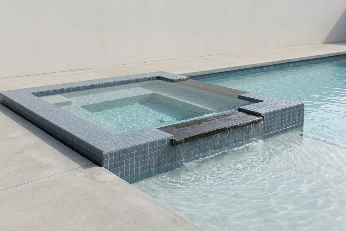
Write where water comes from and where it returns in each mode. In the shared-loop example, spillover draws from the pool and sends some return water to the spa; once the spa reaches the crest, water returns over the weir. Spa recirculation instead pairs spa suction with spa return. These are path descriptions, not pump-speed or valve-angle settings.
Swipe table horizontally to read all columns.
Scroll horizontally to see all columns →
| Mode | Suction → return | Heat and observation | Dominant Failure Mode & Prevention |
|---|---|---|---|
| Pool circulation | Pool → pool; any spa branch must be documented | Pool heating duty if enabled | Unplanned spa feed changes levels; verify actual return split |
| Spillover | Pool → spa branch → weir → pool | Record feature runtime and receiving-pool conditions | Excess feature flow wastes pumping and splash water; commission the accepted effect at measured flow |
| Spa recirculation | Spa → spa; pool paths isolated as designed | Spa heating only with required flow proven | Mismatched intake/return drains or dilutes spa; verify paired changeover |
| Pump off | No intended circulation; review every connected reverse path | After crest runoff settles, record water levels over the agreed test period | Leaking check or diverter permits transfer; locate the path before replacing parts |
Pentair’s IntelliCenter installation guide distinguishes shared filtration from dual equipment on printed page 17. Its IntelliValve manual, page 12 illustrates partial pool/spa return splitting for a spillway effect. The illustrated endpoints belong to that product example; an endpoint index is not a measured flow fraction. Confirm the installed port orientation and actual flow at handover.
Have the installer verify travel direction, both end stops and the controller’s documented pump/heater behavior during changeover. Confirm minimum equipment flow and interlocks from the selected manuals in each permitted mode. Do not copy a generic delay or energize a heater against an unverified path. Keep the measurements with the equipment commissioning record.
Check pump-off reverse flow without assuming the failed part
A return-line check valve blocks reverse flow only through its own path. An elevated spa can still transfer water through another connection, including a diverter that does not seal the intended branch. Record the settled spa and pool levels, controller mode, autofill state and other water uses; a falling spa level alone does not distinguish pipe transfer, evaporation and a vessel leak.
The Jandy check-valve instructions, 7303 Rev G describe horizontal or upward-flow vertical mounting and use of the water column to assist sealing. Those instructions are specific to that valve family. Check the selected valve’s flow direction, orientation and installation limits rather than treating any transparent-lid valve as interchangeable.
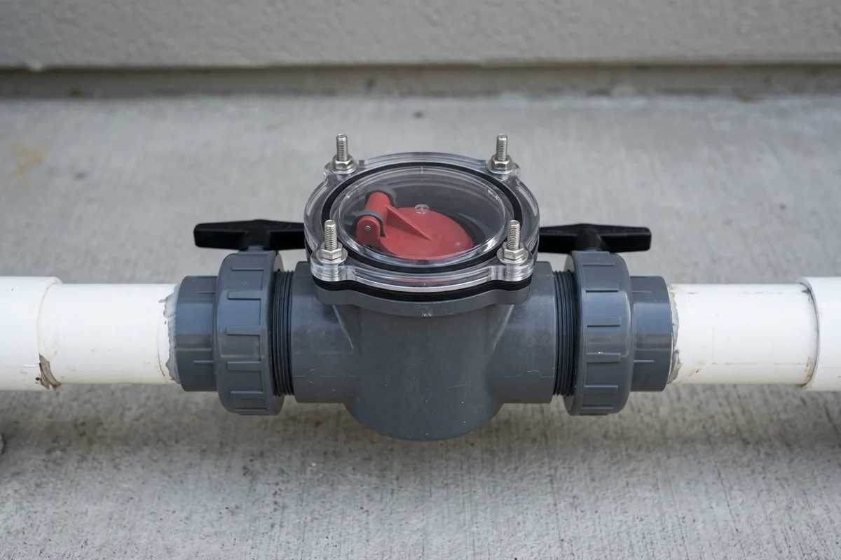
Use the installer’s safe isolation procedure for diagnosis. The Jandy manual requires the pump and its electrical supply to be off before valve work. Before opening any closure, the qualified maintainer must also follow the system’s pressure-release instructions. Keep lids accessible and record the observed seal condition; replacing a flapper cannot repair a separate leaking suction diverter.
Screen weir-scale risk using measured water balance
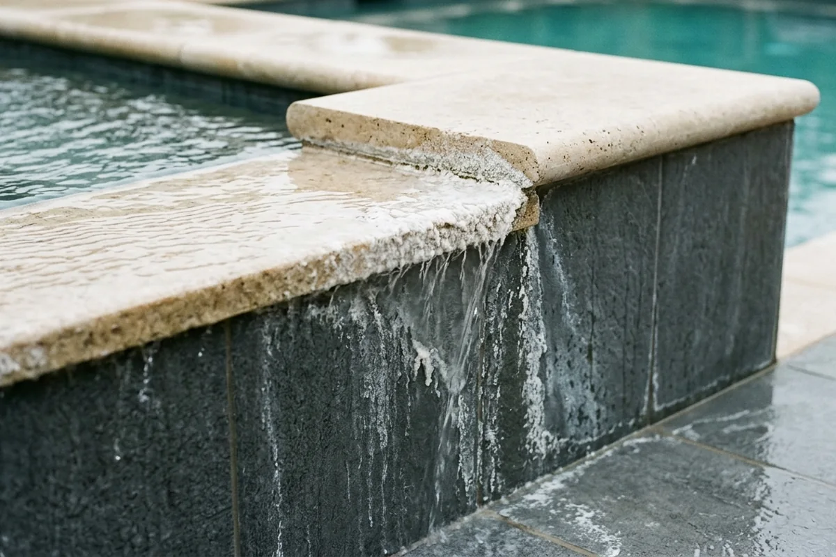
Use chemistry measurements to assess scale tendency before choosing a cleaning treatment. The CDC’s 2024 MAHC Annex, sections 5.7.4.4 and 5.7.4.6 identifies pH, temperature, hardness, alkalinity and dissolved solids as water-balance inputs. LSI screens calcium-carbonate scale tendency; it does not identify every white deposit or replace disinfectant control. Confirm deposits and finish compatibility before cleaning; no acid recipe follows from an index value.
Formula: LSI = pH + TF + CF + AF − TDSF, using the Annex Table 5.7.4.6 factors for temperature, calcium hardness, total alkalinity and total dissolved solids.
Worked line — labeled assumptions: Assume pH 7.8, sample temperature 34°C (TF 0.8), calcium hardness 400 mg/L (CF 2.2), total alkalinity 100 mg/L (AF 2.0), and TDS 1500 mg/L (TDSF 12.2): LSI = 7.8 + 0.8 + 2.2 + 2.0 − 12.2 = +0.6. These are hypothetical sample inputs, not target bathing or dosing conditions.
Rule of thumb: If calculated LSI is above +0.3 under the measured sample conditions, prioritize water-balance review before repeating cosmetic weir cleaning. The Annex associates values above +0.3 with scale formation and gives a reference band of −0.3 to +0.3. Use the applicable treatment and finish requirements; the band is not a dosing instruction or a guarantee of a clean edge.
The 2024 MAHC Code, section 5.7.5.8 calls for monthly saturation-index checks within its public-aquatic model framework. Local adoption determines enforceability. Keep chemistry observations and actual feature runtime in the pool and spa maintenance log.
Record heat, water and service costs at handover
Log spillover runtime, pump electricity, makeup water and spa heat-up behavior separately. Water transferred back to the pool is not automatically water lost from the property; splashed or evaporated water and deliberate drain/refill are different costs. Reheating cooler replacement water and opening an inaccessible valve add energy or downtime without a visible equipment fault.
Use the energy operating record to compare the same weather and cover conditions. Check cover operation and travel when the spillway runs. Keep weir waterproofing, release-edge geometry, splash and waterfall planning in the raised spillover spa waterfall guide; changing those details is a separate design decision.
Swipe table horizontally to read all columns.
Scroll horizontally to see all columns →
| Handover record | Project entry | Acceptance evidence |
|---|---|---|
| Mode/changeover | Schematic / ports / endpoints / flow / heater interlock: ____ | Installer observes each permitted mode and transition |
| Pump-off behavior | Initial/final levels / times / autofill / weather: ____ | After crest runoff, investigate unexplained continued transfer |
| Check-valve service | Selected manual / orientation / lid clearance / isolation: ____ | Safe access retained and actual path confirmed |
| Scale and runtime | Sample date / pH / TF / CF / AF / TDSF / LSI / hours: ____ | Chemistry and finish requirements reviewed together |
Method and sources
Reviewed 19 October 2026 from the linked Pentair controller and actuator guides, Jandy 7303 Rev G instructions, and CDC 2024 MAHC Code and Annex. The mode table is an editorial shared-loop review example; installed controls and equipment instructions supply the settings. The LSI worked line uses the Annex factors and explicit hypothetical inputs. The MAHC is a public-aquatic model framework, not an automatic private-residential legal requirement. Photos illustrate component access and surface conditions, not a commissioned customer system.