
Custom Inground Hot Tub Planning: Seat Depth, Step Benches, Footwell and Cover-Recess Allowance
A custom inground hot tub can need concrete and deck rework when the seating and cover housing are left to separate drawings. Plan seat depth, step benches, footwell and cover-recess allowance on one finished-dimension record before fixing the shell outline.
Plan a custom inground hot tub from its finished internal surfaces outward. Record usable horizontal seat depth separately from water above the seat, trace the entry steps into the occupied footwell, and reserve the selected cover system’s housing, drainage and service space. Use the tables below as a drawing-review record: project measurements and supplier details supply the values. This coordination step prevents a bench, coping change or cover box from consuming space that another drawing assumes is clear.
Start with the in-ground spa design brief to settle users, operating duties and cover type; this page coordinates the resulting dimensions.
Swipe table horizontally to read all columns.
Scroll horizontally to see all columns →
| Input or item | Value or source | Why it matters |
|---|---|---|
| Finished internal width | Measure the stated plan section, after finish allowance | Sets the space shared by benches and footwell |
| Usable seat depth | Measure back-support surface to front edge horizontally | Distinguishes sitting room from immersion |
| Step and bench levels | Dimension each finished tread and seat on the section | Shows the transition into the seating area |
| Footwell occupancy | Measure intended users’ foot positions and entry route in a mock-up | Reveals conflicts hidden by an empty plan |
| Cover recess | Selected supplier’s coordinated housing and access drawing | Reserves more than the visible lid footprint |
Measure seat depth from finished support surfaces
Specify horizontal seat depth and vertical seat immersion as separate dimensions. A deeper horizontal bench can take space from the footwell without changing the water above the seat. Mark the exact front edge and back-support point, especially where a curved backrest changes the usable sitting area.
Spectrum Aquatics’ in-ground spa measuring form separates bench width, wall slope, water draft, top-to-seat and total depth. It is a field-measurement form, not a comfort specification. Transfer that separation to the project drawing and identify whether each dimension starts at coping, waterline or floor.
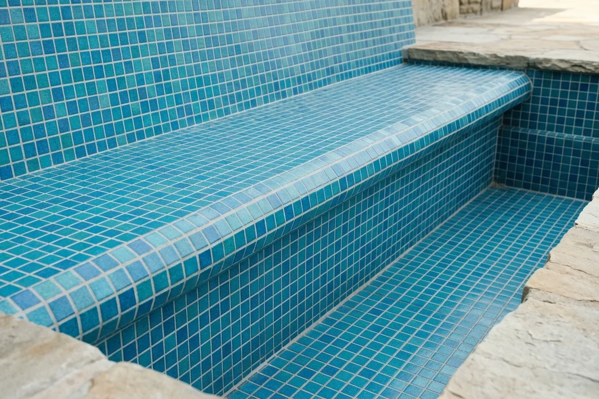
Use the seat immersion and waterline schedule for the preferred water level above each seat. Then review seat fit and jet-contact zones against that same section. A dry mock-up can expose reach and clearance issues; submerged comfort still needs an appropriate in-water observation.
Treat step benches as a route as well as a seat
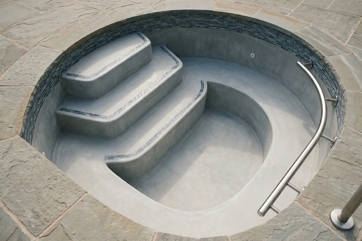
Draw the approach, each finished tread and the transition to the footwell before assigning seats. If a step also becomes a sitting place, check what happens when it is occupied: another person must still have a reviewed way to enter and leave. Record tread depth, riser height, edge profile and handhold location from the project design; do not use a seating label to omit the entry review.
For facilities within the scope of the 2010 ADA Standards, section 242.4, spa accessible entry is reviewed separately under the lift, transfer-wall or transfer-system provisions. Ordinary tiered seating does not establish that compliance. Follow the public spa entry review and the applicable local requirements; neither supplies a universal minimum depth for a recreational seat.
Calculate the footwell left after bench projections
Calculate clear width at each critical cross-section, then compare it with the occupied layout. Opposed benches, curved corners and an entry tread can create different pinch points. Include the selected suction fittings and their required installation clearances in the designer’s review; a grate is not a foot support or a place to stand during fitting.
Formula: F = W − B₁ − B₂. F is finished clear footwell width; W is finished internal width; B₁ and B₂ are the opposing bench projections at the same section. Use one unit throughout.
Worked line — labeled assumptions: Assume a measured proposal W = 2400 mm, B₁ = 500 mm and B₂ = 500 mm: F = 2400 − 500 − 500 = 1400 mm. These illustrative drawing inputs are not recommended construction dimensions or code minima.
Rule of thumb: If F minus the measured occupied-feet and agreed entry-route envelope is zero or negative, revise the layout before shell approval. This is a geometric conflict threshold, not an access-code clearance. A positive remainder still needs the designer’s review.
Swipe table horizontally to read all columns.
Scroll horizontally to see all columns →
| Layout choice | Check on the drawing | Dominant Failure Mode & Prevention |
|---|---|---|
| Opposed benches | Both projections and occupied foot positions | Feet overlap at the narrow section; revise projections using an occupied mock-up |
| Step bench at entry | Approach with the seat occupied | Occupied tread obstructs passage; preserve a reviewed entry route |
| Deep recess behind coping | Housing, structure, drainage and lid removal | Finish traps the mechanism; coordinate removable access before deck work |
Reserve the selected cover recess and its service envelope
Use a supplier drawing for the complete recess allowance. Record clear box width and depth, motor-end space, opposite-end space, throat, beam interface, lid support, drainage outlet and removal access. The visible lid size alone does not establish whether the roll and drive will fit.
The Cover-Pools installation overview, 800024 Rel-0024 shows separate spa-housing configurations for different motor and conduit positions on printed pages 8–9. It also shows housing drainage and coping interfaces. This 2015 overview demonstrates the coordination required; obtain the current selected system’s accepted shop drawing rather than copying its historic box dimensions.
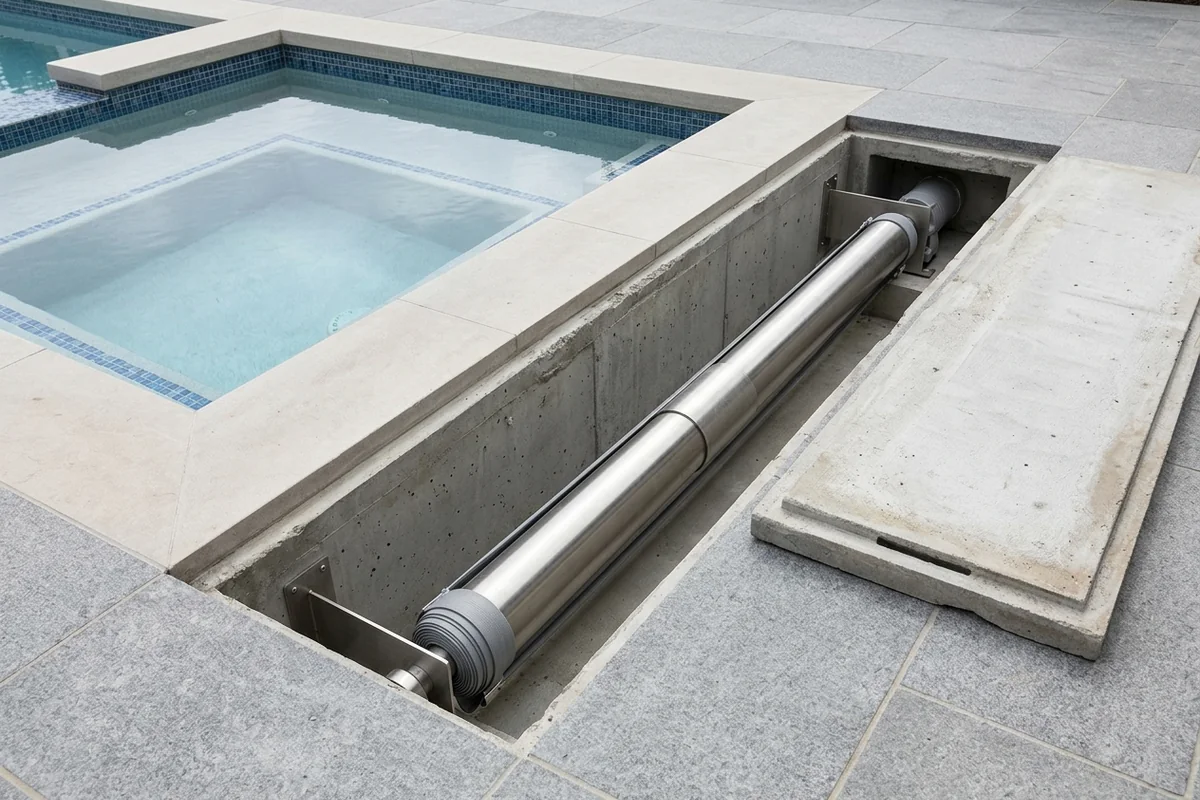
If the selected cover uses another storage arrangement, record its actual opening and removal envelope instead of adding a redundant pit. Review the cover-system requirements before fixing coping and deck geometry.
Close the dimension record before concrete and deck work
Keep the measurement, drawing revision and reviewer together. An unresolved dimension remains a named action for the responsible designer or supplier; it is not filled with a generic catalog size.
Swipe table horizontally to read all columns.
Scroll horizontally to see all columns →
| Record | Project entry | Release check |
|---|---|---|
| Seat and waterline | Seat ID / horizontal depth / water-over-seat / units: ____ | Finished support points and section revision agree |
| Steps and footwell | Treads / risers / F / occupied envelope / remaining clearance: ____ | Route and suction-fitting review complete |
| Cover recess | Supplier / drawing / clear box / drain / service envelope: ____ | Coping, lid and structure coordinated |
| Acceptance | Reviewer / revision / open actions / date: ____ | Reissue affected drawings after a change |
Hidden operating cost follows the geometry: a lid that cannot close leaves a planned covered period unavailable, while a trapped mechanism can turn maintenance into deck work. Record actual uncovered hours and the supplier’s access procedure in the heat and cover operating record. No fixed energy saving follows from the outline alone.
Carry the accepted record into the architectural spa construction review so shell, reinforcement, fittings and finishes use the same revision.
Method and sources
Reviewed 19 October 2026. This guide combines the Spectrum measuring form, Cover-Pools 800024 Rel-0024 and U.S. Access Board 2010 ADA Standards linked above. The dimension tables are editorial review records; the worked line uses explicit hypothetical measurements. Supplier instructions and applicable adopted requirements control the project. Photos illustrate geometry and access, not an approved construction detail.