
Concrete Spa Shell Thickness and Rebar Schedules
A shell specification copied from another spa can leave critical steel positions and construction checks unresolved. Read thickness, reinforcement and strength from the same project design, then check how those requirements will be built and verified.
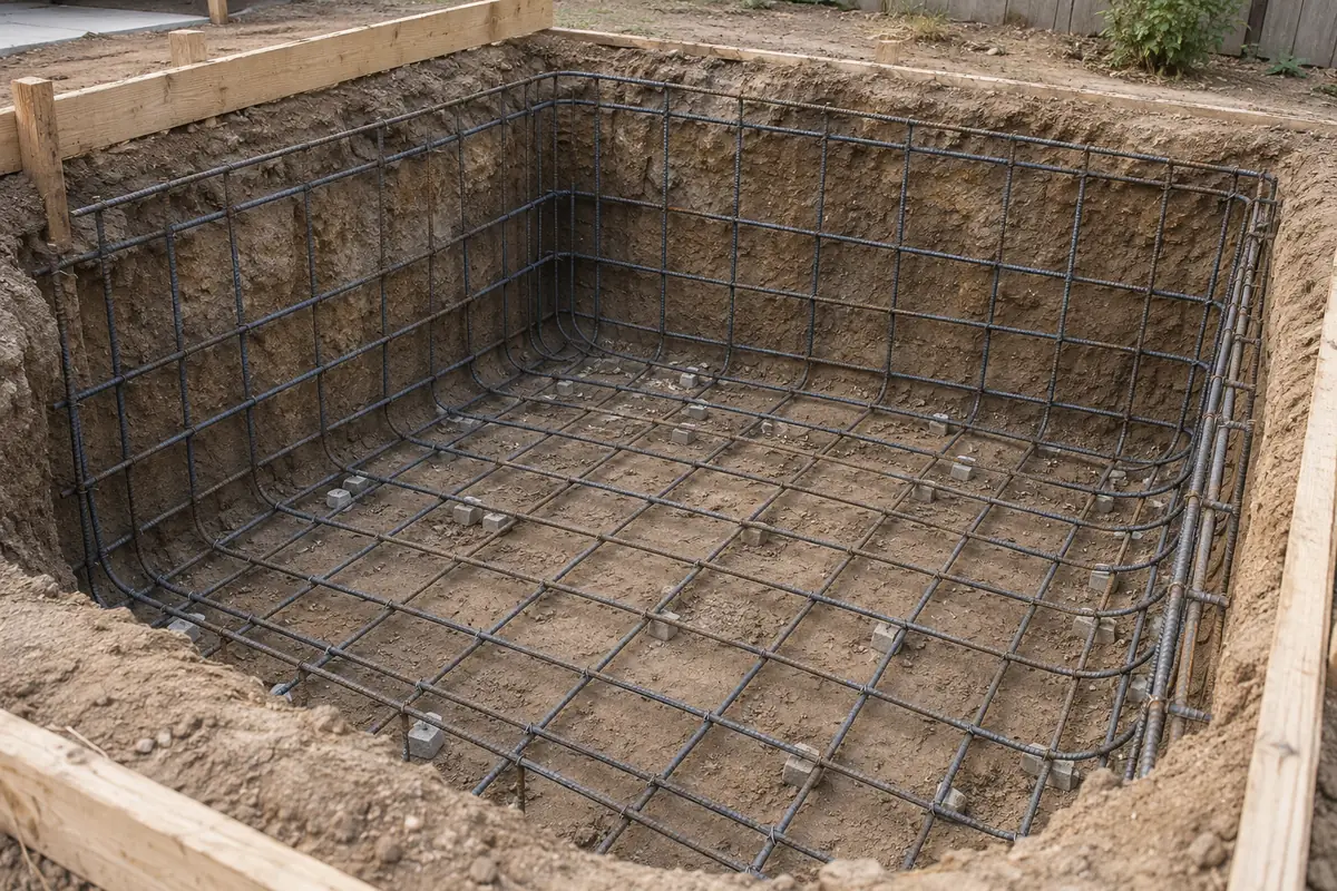
Concrete spa shell thickness and rebar spacing are project design outputs, not a universal grid. This guide helps owners of site-built residential spas compare a shell proposal with its drawings: what each dimension means, what belongs in the steel schedule, and which records distinguish specified concrete strength from completed work. It supplies review questions, not construction dimensions or a calculation for your site.
- Separate structural shell dimensions from the finish build-up.
- Read steel quantity together with its position and cover.
- Check placement, testing and curing before hiding the work.
Shell review at a glance
Start with a coordinated set of documents. A verbal promise of a thick shell or a strong mix leaves several separate decisions unanswered. Use this table to locate the design requirement and the corresponding construction record before comparing proposals.
Scroll horizontally to see all columns →
| Item | Where to find it | What to check |
|---|---|---|
| Wall, floor and transition thickness | Structural sections and details | Dimension limits, changes in section and finish allowance |
| Bars and spacing | Reinforcement plan and schedule | Direction, location, layer and zones with different requirements |
| Cover, laps and anchorage | Structural notes and junction details | Clear distance to surfaces and how bars continue or terminate |
| Specified strength | Concrete specification and test plan | Strength, test age, sampling and acceptance responsibility |
| Curing and finish interface | Construction plan and selected material instructions | Who maintains moisture, protects the shell and releases it for finishing |
Set the spa’s geometry first through the in-ground spa design hub. For the site survey and design-team inputs, use the architectural spa construction guide.
Takeaway: Compare document-backed requirements, not isolated numbers in a quote.
What does shell thickness actually describe?
Ask which surfaces bound the structural dimension. A section showing concrete, a waterproofing assembly and tile should make those layers distinguishable. Write down whether a quoted dimension is concrete thickness or the overall finished assembly; return an ambiguous dimension to the designer rather than subtracting an assumed finish allowance.
Follow the section through the floor, wall, bench, steps and wall-to-floor transition. A single dimension on a typical wall does not explain every junction. The ASA reinforcement article discusses benches, beams, plumbing and excavation changes as areas where bar position or the section can go wrong. Ask for the relevant detail when the drawing changes direction or shape.
A raised or exposed wall also deserves its own review. Coordinate it with the spillover spa interface guide and the adjacent deck and retaining structures in the pool and spa layout plan. Changing the section is a design question to resolve before the crew works from it.
Takeaway: Locate thickness on a section, then check every change in geometry against its own detail.
How do you read the rebar schedule?
Read the schedule as a set of location instructions. Bar size alone cannot describe the reinforcement. Center-to-center spacing describes the repeating grid; clear spacing describes the opening between bars; cover describes the concrete between steel and the nearest concrete surface. These are different checks.
Scroll horizontally to see all columns →
| Schedule field | Review question |
|---|---|
| Bar designation and material | Does the supplied steel match the drawing’s designation and notes? |
| Spacing and direction | Which wall or floor zone does the callout cover, and does it apply in both directions? |
| Layer and position | Is the detail showing one layer or multiple layers, and where is each located? |
| Concrete cover and supports | How will the specified position be maintained during placement? |
| Laps, bends and anchorage | Which detail controls continuity at corners, steps and wall-to-floor junctions? |
| Openings and embedded items | Are pipes and fittings coordinated without moving bars out of their detailed positions? |
The ASA article explains that embedded steel contributes to the shell’s resistance to bending and flexing, while closely packed bars can obstruct shotcrete encasement. If a calculation lists a reinforcement ratio, ask the designer to identify the corresponding bars and concrete section on the drawings and explain how the proposed arrangement will be placed.
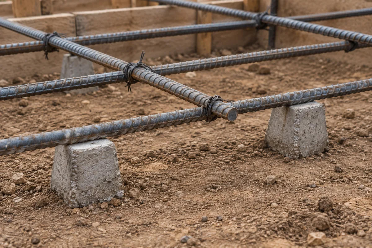
Place penetrations on the same drawing as the cage, using the equipment coordination checklist to keep pipe and fitting locations visible.
Takeaway: Read steel amount, position, continuity and placement access together.
What does compressive strength prove?
A strength result answers a material-testing question. It does not document the shell’s dimensions or the location of its bars. Specified compressive strength, often written f′c, belongs in the project specification with its test age; laboratory results are separate records to compare with the accepted test plan.
The ASA’s Summer 2018 pool guidance advocates a minimum 28-day compressive strength of 4,000 psi for pool shotcrete. That is the published industry position discussed in that issue, not a universal local-code requirement or a strength measured in your spa. Have your designer identify the applicable project requirement rather than replacing it with this figure.
NRMCA’s CIP 35 explains why test age and specimen handling matter. For sprayed material, the NRCS shotcrete chapter describes taking strength specimens from sprayed test panels. Ask who specifies sampling, who tests the specimens and how results will be linked to the shell placement. A mix submittal or delivery ticket alone is not that test report.
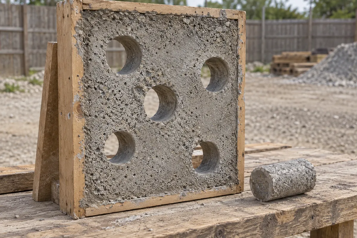
Takeaway: Compare strength results with the specified test conditions; check geometry and steel separately.
How do heat, shrinkage and curing affect crack control?
Crack control involves movement and restraint as well as strength. NRMCA’s CIP 4 explains that concrete changes volume with moisture and temperature and deflects under load. Reinforcement can help control crack width, but it does not make concrete incapable of cracking. A hot-water temperature alone cannot define a steel schedule or a thermal stress calculation.
Scroll horizontally to see all columns →
| Issue to separate | Question for the project team |
|---|---|
| Early moisture loss | What protection and curing method will be used on walls, floor and exposed edges? |
| Temperature changes and restraint | Which construction and operating conditions were considered, and what joint or transition details follow? |
| Support or geometry changes | Has the designer reviewed the changed excavation, nearby structure or revised bench? |
| Finish interface | Is the curing method compatible with the selected bonded finish or waterproofing system? |
CIP 11 describes curing as maintaining suitable moisture and temperature for cement hydration. It cautions against alternating wetting and drying as moist curing and discusses temperature differentials and curing materials that may affect later bonded coverings. Put the selected method, responsibility and completion criteria in the construction plan. An admixture’s name is not a substitute for that plan.
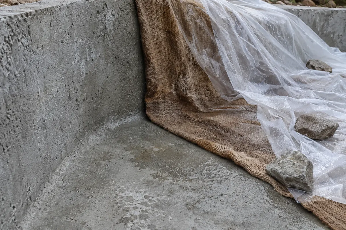
Record intended heating and cover operation with the spa energy planning guide. Keep water-temperature and user-safety decisions with the pool and spa safety guidance; those limits do not establish structural dimensions.
Takeaway: Ask how the project handles moisture loss, temperature change and restraint; do not accept a crack-free guarantee from one specification.
What should be checked before the cage is covered?
Arrange the review while steel and substrate remain visible. This is a document-and-observation checklist for the project team, rather than an owner’s substitute for a required inspection. Put unresolved discrepancies back to the responsible designer before approving concealed work.
- Confirm that the crew, designer and inspector are using the same drawing revision.
- Match wall, floor, bench and junction details to the prepared excavation and forms.
- Check bar designations, directions, positions, cover, supports and splice details against the drawings.
- Resolve conflicts at pipes, fittings and tight corners; confirm placement access behind steel.
- Check that steel and the receiving surface are ready, with debris and accumulated rebound addressed.
- Confirm the material-test and curing responsibilities, then retain the inspection and placement records.
Photographs can record visible conditions at this stage; they cannot verify every concealed feature afterward. Keep these records with the owner’s maintenance and handover information so a later investigation can compare observed conditions with the original construction documents.
Takeaway: Resolve discrepancies while they can still be seen, and retain the records for handover.
When this does not apply
This review is for site-built residential concrete spa shells. It does not design a foundation for a portable hot tub, specify a factory-built shell, classify an existing crack or prescribe its repair. Public and commercial facilities need a separate review of applicable requirements; begin with the commercial aquatic design hub. Local adoption, project engineering and selected materials govern the actual requirements. General slab joint-spacing or curing examples should not be transferred to a water-retaining shell as construction instructions.
Takeaway: Use this as a specification-reading aid; have the appropriate project professional resolve the design and acceptance decisions.
Frequently asked questions
Is gunite stronger than shotcrete?
Gunite usually means dry-mix shotcrete, so the names alone do not establish a strength difference. Compare specified strength, test age and the accepted test results. A process name does not demonstrate the thickness or reinforcement of a particular shell.
How many psi is shotcrete?
There is no single strength for every shotcrete application. Read the specified strength and test age in the project documents, then the laboratory results. The ASA pool guidance discussed above is an industry recommendation, not a measured result for your spa.
Can you pour gunite in the rain?
Gunite is sprayed rather than poured. Ask the crew and inspector to assess the actual excavation, substrate and steel before proceeding. The ASA reinforcement article describes rain-related soil collapse as a reason to clean the cage, restore its position and consult the designer if the section changes.
What are the disadvantages of shotcrete?
For a reinforced spa, access behind bars, substrate condition and workmanship need close attention. Dense steel can obstruct placement. An attractive finished surface cannot by itself establish complete encasement; the placement and inspection plan should address the concealed work.
How does one diagnose the true cause?
For an existing shell crack, begin with the original drawings, any changes, construction and curing records, dated photographs and observations of leakage or movement. Ask a qualified structural professional to assess the site. A photograph or strength figure alone cannot identify the cause.
How do I ensure that it gets fixed correctly and not a bandaid?
Request a written assessment of the crack, the proposed repair scope and how the repair will be checked. Have the structural and finish responsibilities coordinated before covering the area. This construction-review guide does not select a repair product or certify a damaged shell.
Method and sources
Compiled from the public technical publications below, reviewed October 9, 2026. The tables organize questions for a project review; they are not a structural design, site assessment or report of our own tests. ASA’s pool guidance is an industry source, NRCS describes construction inspection, and the NRMCA sheets explain concrete behavior. None replaces your project documents or establishes which code edition your jurisdiction has adopted.
- ASA, Shotcrete, Summer 2018: reinforcement article, printed pages 18–20; pool strength discussion, pages 12 and 29.
- USDA NRCS, National Engineering Handbook, Part 645, Chapter 14: Shotcrete (April 2017), installation and sampling sections.
- NRMCA CIP 4: Cracking Concrete Surfaces (2014), movement, restraint and reinforcement.
- NRMCA CIP 11: Curing In-Place Concrete (2017), moisture, temperature and curing methods.
- NRMCA CIP 35: Testing Compressive Strength of Concrete (2014), specified strength and test conditions.
Sources accessed October 9, 2026. All photographic illustrations are generated explanatory images.
Related reading
- In-ground spa design — settle the seating and overall geometry before detailed shell review.
- Raised spillover spa planning — coordinate the exposed edge and adjoining pool interface.
- Pool and spa equipment — coordinate fittings and equipment with structural drawings.
Takeaway: Bring the shell questions back to a coordinated design, with the layout and equipment interfaces resolved.