
Hydrotherapy Jets: Venturi Air, Hartford Loop, and Booster Pump Sizing
A hydrotherapy jet fitting blends air and water into a turbulent stream on a dedicated loop kept independent of spa recirculation, filtration, and heating.
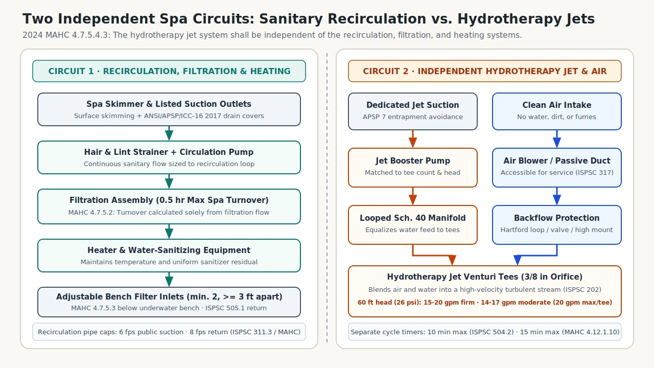
Under the International Swimming Pool and Spa Code (ISPSC, 2021), a hydrotherapy jet is a fitting that blends air and water, creating a high-velocity turbulent stream of air-enriched water, while an air induction system introduces air into hollow ducting built into a spa floor, bench, or hydrotherapy jets. Under MAHC Sections 4.7.5.4.3, 4.7.5.2.1, and 4.7.5.2.2, the hydrotherapy jet system shall be independent of the recirculation, filtration, and heating systems, and the 0.5 hour maximum allowable turnover time is calculated solely from flow through the filtration system: International Swimming Pool and Spa Code (ISPSC, 2021) · CDC Model Aquatic Health Code (MAHC, 2024).
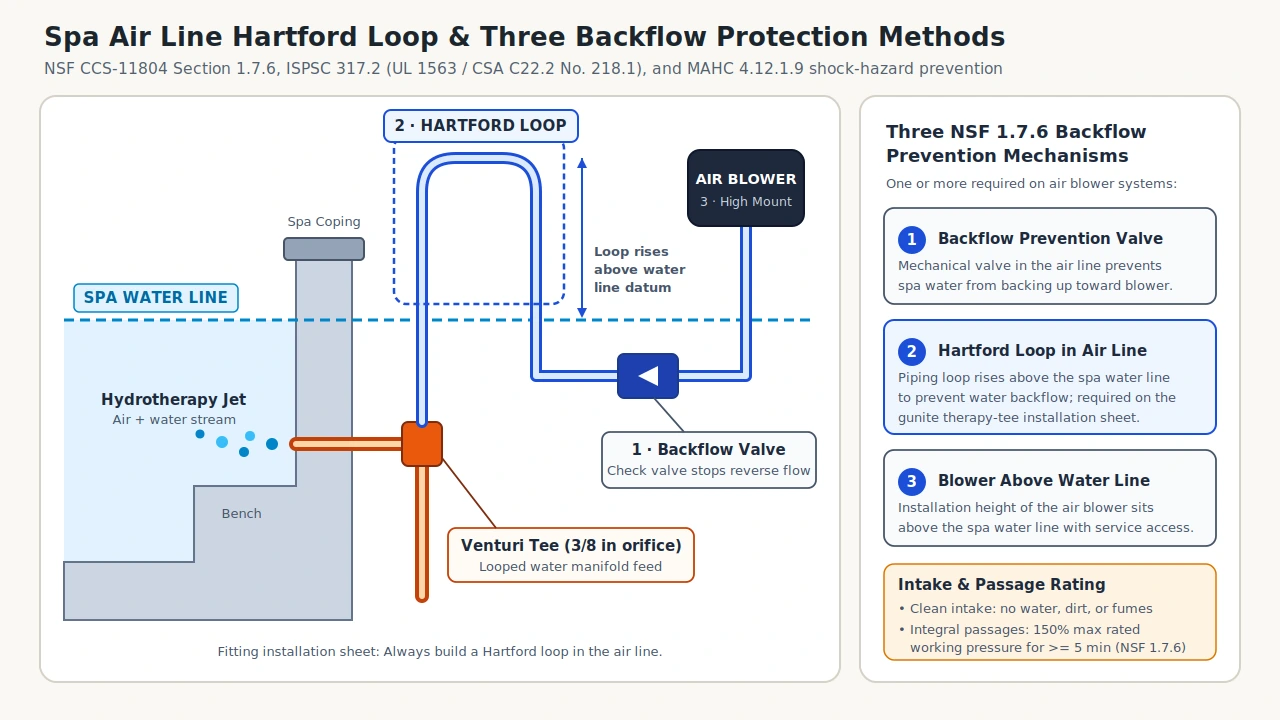
On a gunite therapy-tee installation sheet, each venturi tee uses a 3/8 inch orifice on a looped jet manifold requiring 15-20 gpm each at 60 feet of head for a firm stream, or 14-17 gpm each for a moderate stream, with flow capped at 20 gpm per tee so every jet works properly. Air blower and air induction lines prevent water backflow through a backflow prevention valve, a Hartford loop rising above the water line, or a blower mounted above the water line.
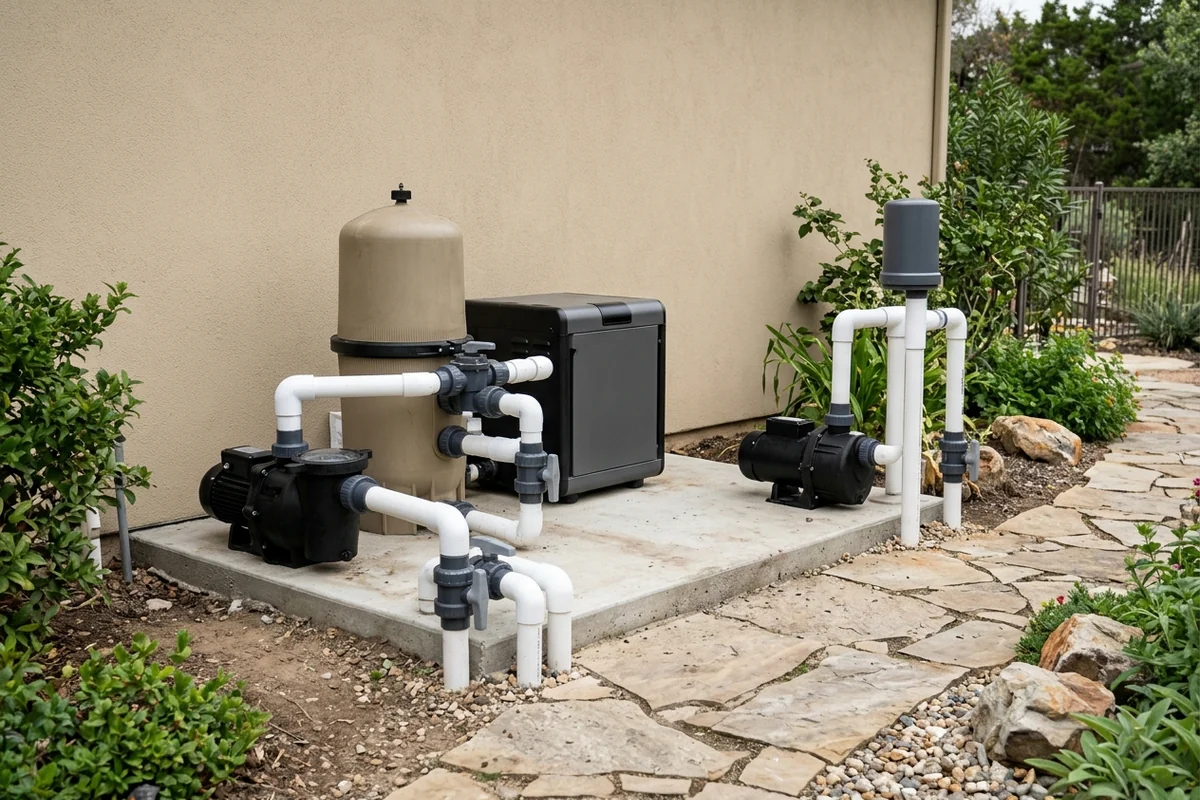
For equipment-pad pump allocation where the circulation and filter pump serves treatment equipment and the spa jet circuit serves the jet zones, see pool and spa equipment alongside shell layout considerations in in-ground spa design.
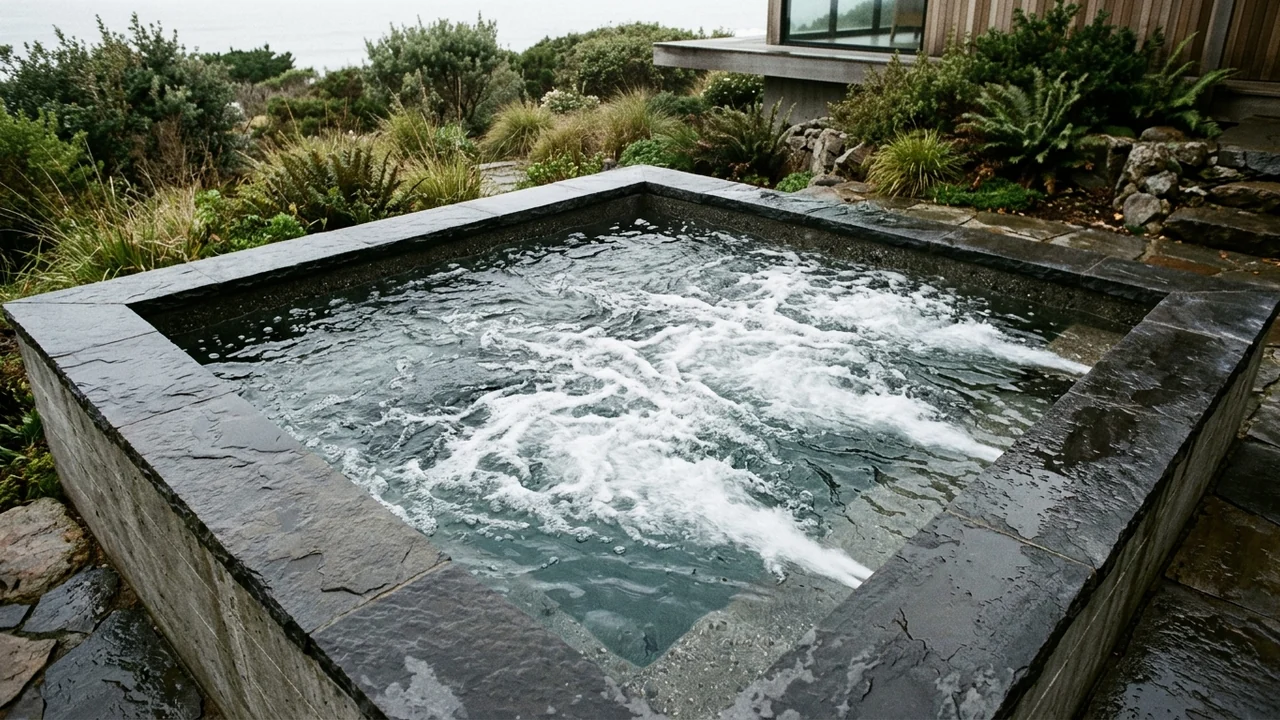
How Do Hydrotherapy Jets Differ From the Filtration Loop?
Under the ISPSC definition, a spa is a product for immersing people in temperature-controlled water circulated in a closed system and is not intended to be drained and filled with each use; it usually includes a filter, a heater, a pump or pumps, and a control, and can include lights, blowers, and water-sanitizing equipment. In the International Swimming Pool and Spa Code (ISPSC, 2021), the defined term recirculation system cross-references the circulation system, whose pumps, hair and lint strainers, filters, valves, gauges, meters, heaters, surface skimmers, inlet and outlet fittings, and chemical feeding devices keep water clear and sanitary, with Section 505.1 arranging return fittings for uniform circulation and sanitizer residual.
In the CDC Model Aquatic Health Code (MAHC, 2024), Section 4.7.5.4.3 requires the hydrotherapy jet system to be independent of the recirculation, filtration, and heating systems, while Section 4.7.5.4.1 permits air flow through the hydrotherapy jet system and/or when injected post-filtration. Spas under Sections 4.7.5.2.1 and 4.7.5.2.2 have a maximum allowable turnover time of 0.5 hour or less calculated solely from the filtration flow rate, and Section 4.7.5.3 requires at least two adjustable filter-system inlets located below the surface of the underwater bench and spaced at least 3 feet (0.9 m) apart; full turnover and suction-outlet coverage is detailed in commercial hot tub code and filtration turnover.
Seat ergonomics and bather contact zones are documented separately by reviewing the finished seat, the person using it, and the selected jet together as a seat-fit record, whereas an exercise spa (swim spa) produces a water flow for swimming in place and has an unobstructed volume of water large enough for the 99th Percentile Man specified in APSP 16, and can pair peripheral jetted therapy seats with separate controls: hydrotherapy jet positioning and ergonomics · swim spa vs. pool hydraulic load.
How Do You Size a Spa Jet Booster Pump?
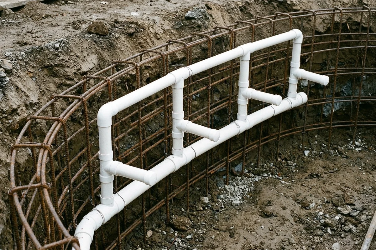
Size a dedicated spa jet booster pump from the installed therapy-tee count and operating head rather than motor nameplate horsepower. On the gunite therapy-tee installation sheet, each venturi tee requires a 3/8 inch orifice inside the tee, and plumbing of the jet manifold must be looped to equalize feed across the bench.
At 60 feet of head, those 3/8 inch orifice tees require 15-20 gpm each for a firm stream and 14-17 gpm each for a moderate stream. Flow above the maximum 20 gpm at each tee causes some of the jets not to work properly, so total booster demand stays inside the per-tee band and the sheet's Schedule 40 PVC pipe columns.
Maximum Flow Rates for Schedule 40 PVC Pipe and Therapy-Tee Demand
Scroll horizontally to see all columns →
| Row / Velocity Basis | 1-1/2 in Pipe | 2 in Pipe | 2-1/2 in Pipe | 3 in Pipe | 3/8 in Orifice Tee (@ 60 ft Head) |
|---|---|---|---|---|---|
| Suction: Nominal GPM @ 6 fps | 38 gpm | 63 gpm | 90 gpm | 138 gpm | 15-20 gpm each for firm stream |
| Return: Nominal GPM @ 8 fps | 51 gpm | 84 gpm | 119 gpm | 184 gpm | 14-17 gpm each for moderate stream |
Worked Sizing Example: Tee Count, Head Conversion, and Continuity
Worked example in the 2-1/2 inch suction column (90 gpm nominal at 6 fps): dividing 90 gpm by the 15 gpm firm-stream floor yields 6 therapy tees (90 gpm ÷ 15 gpm = 6). At the 20 gpm per-tee ceiling, an assumed 4-tee bench draws 80 gpm and stays within the 90 gpm column, whereas an assumed 5-tee bench at 20 gpm draws 100 gpm and steps up to the 3 inch suction column (138 gpm at 6 fps).
Using 1 psi = 2.31 feet of head, dividing the fitting sheet's 60 feet of head by 2.31 equals 25.97 psi, and the same sheet lists 1 foot of head = 0.433 psi. Pipeline continuity follows Q = A × V, written for circular pipe as Q (cfs) = 0.785 × (Diameter, ft)² × (Velocity, fps), with 1 cubic foot = 1728 cubic inches, 1 cubic foot of water = 7.48 gallons, and 1 U.S. gallon = 4 quarts = 231 cubic inches: Tennessee TDEC Collection Systems Formulas · NIST General Tables of Units of Measurement (Appendix C).
How Do Venturi Air Blowers and Hartford Loops Prevent Backflow?
Under ISPSC Sections 317.1 through 317.5, the section applies to devices and systems that induce or allow air to enter Class A and residential pools and spas by a powered pump or by passive design. Air blower systems shall carry backflow protection as specified in UL 1563 or CSA C22.2 No. 218.1, air induction systems shall be sized to the manufacturer's specifications, and air blowers shall have access for inspection and service.
Under NSF CCS-11804 Section 1.7.6 for public-use integral systems, an air blower system prevents water backflow toward the device via one or more of three mechanisms: a backflow prevention valve, a Hartford loop (a piping loop rising to prevent water backflow), or installing the blower above the water line, while integral air passages withstand 150 percent of the manufacturer's maximum rated working pressure for a minimum of 5 minutes. On a built-in shell, the gunite therapy-tee installation sheet instructs installers to always build a Hartford loop in the air line.
ISPSC Section 317.3 requires air intake sources not to induce water, dirt, or contaminants, while MAHC Section 4.12.1.9 requires an air induction system to prevent water backup that could cause electrical shock hazards and Section 4.12.1.9.1 requires air intake sources not to introduce toxic fumes or other contaminants; for blower intake placement, ventilation, and acoustic isolation, see equipment vault location, soundproofing, and ventilation.
Which Pipe Velocities, Cycle Timers, and Shutoffs Apply by Code?
ISPSC Section 311.3 bases water-velocity calculations on the design flow rate of each recirculation system, and the MAHC sets the suction and discharge caps on recirculation piping. Under ISPSC Section 311.3, water-velocity calculations use the design flow rate of each recirculation system, capping copper and copper-alloy pipe at 8 fps (2.4 mps), public pools and spas at 6 fps (1.8 mps) in suction piping and 8 fps (2.4 mps) in return piping (Section 311.3.1), and residential pools and spas at 8 fps (2.4 mps) in both suction and return piping (Section 311.3.2); MAHC Sections 4.7.1.7.2.1 and 4.7.1.7.2.2 likewise cap recirculation discharge at 8 feet (2.4 m) per second and suction piping at 6 feet per second (1.8 m/s) unless alternative values carry engineering justification.
Public-spa agitation timers and emergency shutoffs differ by adopted code and occupancy. ISPSC Section 504.2 limits public-spa hydrotherapy jets with a cycle timer set to a maximum of 10 minutes located at least 5 feet (1524 mm) away, adjacent to and within sight of the spa, whereas MAHC Sections 4.12.1.10 and 4.12.1.10.1 require a minute timer not exceeding 15 minutes located out of reach of a bather in the spa. For public spas, ISPSC Section 504.1 requires an accessible emergency shutoff within sight of the spa and between 5 feet (1524 mm) and 10 feet (3048 mm) horizontally from the inside walls that disconnects circulation and jet system pumps and air blowers, while MAHC Sections 4.12.1.11 and 4.12.1.11.2 require a clearly labeled emergency shutoff in that same sight and distance band to stop the motors powering the recirculation system and the hydrotherapy jet system; ISPSC Section 504.1.1 adds an audible alarm rated at not less than 80 decibel sound pressure level and a light near the spa that operates continuously until deactivated, Section 901.2 exempts permanent residential spas from Sections 504.1 and 504.1.1, and Section 313.7 requires its own shutoff for recirculation and jet pumps and air blowers with an exception for residential spas.
Every submerged suction outlet serving a circulation or jet booster pump requires entrapment protection: ISPSC Section 310.1 mandates APSP 7 (ANSI/PHTA/ICC 7) with an exception for portable spas listed to UL 1563 or CSA C22.2 No. 218.1, federal rule 16 CFR Part 1450 requires each swimming pool or spa drain cover manufactured, distributed, or entered into commerce in the United States to conform to ANSI/APSP/ICC-16 (approved August 18, 2017), and 15 U.S.C. § 8003 requires ASME/ANSI A112.19.8 or successor anti-entrapment protection on public spas (effective 1 year after December 19, 2007), defined to include general-public, member-guest, and multi-family residential spas: 16 CFR Part 1450 (CPSC Drain Cover Rule) · 15 U.S.C. § 8003 (Virginia Graeme Baker Act).
Quick-Specs Table: Velocity Caps, Separate Cycle Timers, Shutoffs, and Drain Standards
Scroll horizontally to see all columns →
| Requirement | Specification / Limit | Code / Standard Scope |
|---|---|---|
| Public recirculation pipe velocity | Suction ≤ 6 feet per second (1.8 m/s); return/discharge ≤ 8 feet (2.4 m) per second | ISPSC Section 311.3.1; MAHC Sections 4.7.1.7.2.1 & 4.7.1.7.2.2 (engineering justification exception in MAHC) |
| Residential & copper pipe velocity | Suction and return ≤ 8 fps (2.4 mps); copper and copper alloy ≤ 8 fps (2.4 mps) | ISPSC Sections 311.3 & 311.3.2 (per recirculation system design flow) |
| Jet cycle timer (ISPSC) | Maximum setting of 10 minutes; located ≥ 5 feet (1524 mm) away, adjacent and within sight | ISPSC Section 504.2 (applies to public spas and Chapter 9 permanent residential spas via Section 901.2) |
| Jet minute timer (MAHC) | Does not exceed 15 minutes; located out of reach of a bather in the spa | MAHC Sections 4.12.1.10 & 4.12.1.10.1 (public aquatic venues) |
| Public emergency shutoff | 5 feet (1524 mm) to 10 feet (3048 mm) horizontally from inside walls, within sight | ISPSC Section 504.1 (circulation, jet pumps, blowers) & MAHC Sections 4.12.1.11 / 4.12.1.11.2 |
| Public shutoff alarm & residential exception | ≥ 80 decibel sound pressure level alarm and a light near the spa that operates continuously until deactivated | ISPSC Section 504.1.1; Section 901.2 exempts permanent residential spas from Sections 504.1 and 504.1.1, and Section 313.7 excepts residential spas from its own shutoff |
| Spa filtration turnover & inlets | ≤ 0.5 hour from filtration flow only; ≥ two adjustable bench inlets ≥ 3 feet (0.9 m) apart | MAHC Sections 4.7.5.2.1, 4.7.5.2.2, 4.7.5.3 & 4.7.5.4.3 (jets independent) |
| Air blower backflow & pressure test | Valve, Hartford loop, or blower above water line; integral passages 150% max working pressure for 5 minutes | NSF CCS-11804 Section 1.7.6 for the three backflow mechanisms and the pressure test; ISPSC Section 317.2 requires backflow protection as specified in UL 1563 or CSA C22.2 No. 218.1 |
| Suction entrapment & drain covers | ANSI/APSP/ICC-16 2017 drain covers; APSP 7 system design; ASME/ANSI A112.19.8 or successor | 16 CFR Part 1450; ISPSC Section 310.1; 15 U.S.C. § 8003 (public & multi-family spas) |
Frequently Asked Questions
Does spa jet booster pump flow count toward the 0.5-hour filtration turnover requirement?
No. Under MAHC Section 4.7.5.4.3, the hydrotherapy jet system shall be independent of the recirculation, filtration, and heating systems, and Section 4.7.5.2.2 calculates the 0.5 hour maximum turnover time solely from the flow rate through the filtration system.
How many 3/8 inch gunite therapy tees fit a 2-1/2 inch Schedule 40 PVC pipe suction line at 6 fps?
On the gunite therapy-tee installation sheet, a 2-1/2 inch Schedule 40 PVC suction line has a nominal flow of 90 gpm at 6 fps, which supports 6 tees at the 15 gpm firm-stream floor (90 gpm ÷ 15 gpm = 6) or 4 tees at the 20 gpm per-tee ceiling (80 gpm).
Why do built-in spas include a Hartford loop on the venturi air line?
A Hartford loop is an elevated piping loop that prevents spa water from backing up through the air line toward an air blower or intake, serving as one of the three backflow mechanisms in NSF CCS-11804 Section 1.7.6 alongside a backflow prevention valve and mounting the blower above the water line.
Sources
- International Swimming Pool and Spa Code (ISPSC, 2021), City of Aspen PDF: Section 202 definitions (hydrotherapy jet, air induction system, spa, circulation/recirculation system, exercise spa) and Sections 310.1, 311.3, 313.7, 317.1-317.5, 504.1, 504.1.1, 504.2, 505.1 and 901.2.
- CDC Model Aquatic Health Code (MAHC, 2024), 5th Edition Code Language: Spa definition and Sections 4.7.1.7.2.1, 4.7.1.7.2.2, 4.7.5.2.1, 4.7.5.2.2, 4.7.5.3, 4.7.5.4.1, 4.7.5.4.3, 4.12.1.9, 4.12.1.9.1, 4.12.1.10, 4.12.1.10.1, 4.12.1.11 and 4.12.1.11.2.
- 16 CFR Part 1450, Virginia Graeme Baker Pool and Spa Safety Act Regulations (eCFR): Mandatory ANSI/APSP/ICC-16 2017 suction outlet fitting assembly (SOFA) drain-cover standard (approved August 18, 2017).
- 15 U.S.C. § 8003, Federal Swimming Pool and Spa Drain Cover Standard (Cornell LII): ASME/ANSI A112.19.8 or successor anti-entrapment requirement (1 year after December 19, 2007) and statutory public pool and spa definition including multi-family residential spas.
- NIST General Tables of Units of Measurement (Appendix C): Exact U.S. liquid and cubic volume relations (1 gallon = 4 quarts = 231 cubic inches; 1 cubic foot = 1728 cubic inches).
- Tennessee Department of Environment and Conservation, Fleming Training Center Formulas: Collection Systems Formulas and Conversions: 1 psi = 2.31 feet of head (1 foot of head = 0.433 psi), 1 cubic foot of water = 7.48 gallons, and Q (pipeline), cfs = 0.785 × (Diameter, ft)² × (Velocity, fps).
- NSF International CCS-11804, Component Certification Specification for Public Use Spa, Swim Spa, Hot Tub or Related Equipment, Section 1.7.6 (air blower backflow mechanisms and 150% maximum rated working pressure test for 5 minutes).
- Gunite therapy-tee fitting installation sheet (Spa Jets Install Manual): Hartford loop air-line instruction, 3/8 inch venturi tee orifice, looped jet manifold, Schedule 40 PVC nominal flow columns at 6 fps and 8 fps, and 15-20 gpm / 14-17 gpm per-tee bands at 60 feet of head.